A Charpy report gives one absorbed energy figure per bar, and a heat of steel or a welding procedure can be accepted or held on those figures. The pendulum that broke the bars has a verification record behind it. The bars themselves came out of a machine shop, and the report rarely says much about how they were made.
ASTM E23 covers notched-bar impact testing of metals by the Charpy (simple-beam) and Izod (cantilever-beam) methods. Its scope lists requirements for test specimens alongside test procedures, reports, test machines and the verification of Charpy machines. For a shop, the specimen requirements come down to a short list of features on a 55 mm bar, and NIST’s Charpy specialists single out two of them, the notch root radius and the ligament under the notch, as the dimensions most able to shift a result.
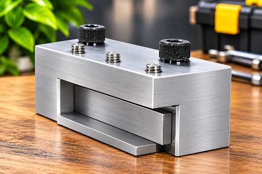
Holding that list starts before any notch is cut. The blank has to be square, to size and repeatable from one bar to the next, and shops bringing impact work in house often begin with workholding. A dedicated fixture for machining Charpy specimen blanks mounts on the machine’s matching base plate and holds the blanks in a controlled position ahead of the final notching or broaching operation. The fixture does not set the dimensions. The drawing and the cited edition of E23 do.
What follows takes the features one at a time, then turns to how laboratories check a bar before it is broken.
A Small Bar With Tight Limits
The standard Charpy specimen is a 55 mm bar with a 10 by 10 mm cross section and a 2 mm deep notch with a 45 degree included angle. It rests against anvils 40 mm apart and is struck on the face opposite the notch, so it behaves like a notched beam loaded in three-point bending.
A 2024 NIST user guide on the dimensional inspection of Charpy reference specimens sets the E23 tolerances (from the 2023 edition, E23-23a) beside NIST’s own. The E23 limits in that comparison are:
- width and thickness, 10 mm, plus or minus 0.075 mm
- length, 55 mm, plus 0.00 mm and minus 2.50 mm
- angle between adjacent sides, 90 degrees, plus or minus 0.17 degree
- notch centering, 27.5 mm, plus or minus 1 mm
- ligament (the material left below the notch), 8 mm, plus or minus 0.025 mm
- notch square to the bar’s long axis within 2 degrees
- notch angle, 45 degrees, plus or minus 1 degree
- notch root radius, 0.25 mm, plus or minus 0.025 mm
Those values belong to the 2023 edition, and ASTM now lists E23-25 as the active version. A shop writing its own specimen drawing should take the limits from the edition its customer cites rather than from a secondary table.
The spread between the numbers says where the test lives. Width and thickness may move 0.075 mm either way, while the ligament is held to 0.025 mm, a third of that band. The tightest limits sit on the notch because the notch is where the bar fails.
Ligament and Root Radius Move the Energy Most
The energy a Charpy bar absorbs is spent starting a crack at the notch root, driving it through the metal below, and deforming the material plastically along the way. That deformation is what leaves the shear lips visible at the edges of a ductile fracture.
The ligament is the metal the crack has to cross. A notch cut slightly deep leaves a smaller ligament and less material to break, and a shallow notch leaves more. Notch depth and ligament describe one dimension from two sides, and NIST measures the ligament directly, from the notch tip to the opposite face.
Root radius controls how sharply stress gathers where the crack begins. A root ground larger than drawn spreads that stress over more metal, while a tighter root concentrates it, and either change alters how readily the crack starts. In the NIST authors’ experience these two features, root radius and ligament, are the ones that can significantly affect Charpy results, which lines up with where E23 places its tightest limits.
Notch angle has a little more room at 1 degree either way, and the requirement that the notch run square across the bar is looser still at 2 degrees either way. NIST holds its own reference bars to plus or minus 0.15 degree on that same perpendicularity, so the E23 figure works as an outer boundary rather than a machining target.
Condition at the bottom of the notch matters for the same reason. Tearing, burrs or a heat-damaged layer at the root change the first material the crack meets, even when the radius itself measures correctly.
Squareness, Length and Centering Decide How the Bar Sits
The remaining dimensions mostly govern how the bar sits in the machine. It lies on supports, against two anvils, with the striker arriving from behind the notch, and out-of-square faces can keep it from seating as intended.
NIST researchers examined whether a bar slightly out of square might tilt at impact, measuring squareness and ligament on a set of super-high-energy reference bars. An earlier NIST study had found no correlation between squareness and energy or fracture mode, and the newer measurements showed no obvious link between those small imperfections and fracture symmetry.
Squareness remains a stated requirement, and a bar outside it does not conform whatever energy it records. Still, a shop chasing scatter should look at the notch before the corners.
Length and notch centering work as a pair. The bar is struck at midspan between the anvils, so the notch has to sit at the middle of the bar for the crack to start under the blow. Where a machine positions the bar from its ends, length and centering together decide where the notch lands. NIST set both for its reference bars so they can be used on machines with end-centering devices, and the same NIST table notes that ISO 148-1 recommends a centering tolerance of plus or minus 0.165 mm where the specimen is positioned automatically.
Order of Operations From Blank to Notch
Sequence protects the notch. Where bars are heat treated, finish machining and notching are normally done after the final heat treatment unless the lab has shown that the order makes no difference. NIST’s reference lots follow that pattern: blanks are cut to about 56 mm, ground to remove surface flaws that might crack during quenching, heat treated, and only then machined to final dimensions.
The blank comes next, with four faces brought to width and thickness, square to each other, and the bar cut to length. The notch is located and measured from those faces, so an error in the blank carries straight into the notch. For labs sizing blanks in modest batches, a compact two-axis machine for flat tensile and impact blanks prepares specimens from metal, plastic and composite stock, generates the toolpath from specimen details entered on a guided touchscreen, and lists its repeatability within plus or minus 0.02 mm. Repeatability is not size on the drawing, so the first bars from a new setup still go to the comparator.
Shops cut the notch by broaching, milling, form grinding or electrical discharge machining. NIST’s reference bars show how strict a producer can be: the notches are form ground on a surface grinder, fly cutters and multi-tooth cutters are not permitted, and the last two passes are limited. The pass before last removes more than 0.25 mm and less than 0.38 mm, and the final pass removes no more than 0.12 mm, specifically to avoid burning or cold working the material at the base of the notch. That is NIST’s rule for reference material, not an E23 clause, but the reasoning applies to any method: light final cuts leave a cleaner root.
Surface finish is part of the specimen requirements in E23 as well. For comparison, NIST holds its reference bars to 1.6 micrometers on the notched face and the face opposite it, and 3.2 micrometers on the other surfaces.
Identification goes on last and away from the notch. E23 keeps markings at least 10 mm from the notch centerline and cautions that some marking methods can heat or deform the bar enough to change its properties. NIST stamps the ends of its bars.
How Labs Check a Bar Before It Breaks
Inspection follows the same list. NIST’s 2024 guide describes a digital optical comparator that measures length, width, notch centering, ligament, notch angle and root radius from the side, ten bars at a time, with thickness measured from the top. Squareness is checked separately with a gauge fitted with a dial indicator, on all four sides of the bar.
Two habits from that procedure transfer easily to a production lab. The notch is cleaned with a hard brush, compressed air and, where needed, a razor blade before it is measured, since debris in the notch reads as geometry. A bar that fails is cleaned and measured a second time before the result stands.
Both faces of the bar count. Toward the end of the 2010s an ASTM interlaboratory study circulated five bars, notched by grinding and by electrical discharge machining, with deliberately varied notch dimensions among 25 laboratories. Participants measured the notch on both sides, because fabrication can vary the notch across the thickness of the bar.
Sampling needs a rule too. NIST inspects 30 bars from a lot of typically 1,900. The lot fails if more than one of the 30 has any dimension beyond twice its tolerance, if more than six have any dimension beyond the tolerance, or if more than three have two or more dimensions out. A shop can borrow that structure for its own batches even while setting its own numbers.
Where the Specimen Hands Over to the Machine
Once a conforming bar leaves the shop, the reading depends on the pendulum. E23 and ISO 148-2 describe two kinds of machine verification. Direct verification inspects the machine itself, including the foundation, frame, hammer, anvils, supports and energy indicator. Indirect verification breaks certified reference bars and compares the result with the certified value.
The indirect check exists because direct inspection alone could not explain unacceptable differences between machines testing similar specimens, and those differences were traced to interactions between machine parts and the specimens. In the United States, the NIST Charpy laboratory in Boulder certifies reference lots at low, high and super-high energy levels for that purpose.
NIST holds those reference bars tighter than E23 on most dimensions to keep specimen variation out of the machine check. Production bars do not need reference-material tolerances, but bars sitting near the edges of the E23 band hand the test lab scatter that a verified pendulum cannot remove.
Questions Shops Ask About Charpy Bar Tolerances
The same five questions come up when a shop starts making Charpy specimens to E23.
- Can a Bar Slightly Outside Tolerance Still Be Tested?
It can be broken, but it does not conform to the method. In a 2026 NIST interlaboratory comparison, one reference bar failed a dimensional check against E23-25 and still gave energy consistent with the rest of its set. One bar settles nothing, and whether a non-conforming result is acceptable is a decision for the customer and the governing specification.
- Are Sub-Size Charpy Specimens Held to Different Notch Dimensions?
ASTM describes sub-size Charpy V-notch specimens in Annex A3 of E23 as keeping the length, notch angle, notch radius and surface finish of the standard bar. Miniaturized specimens under ASTM E2248 are a different case, with all linear dimensions reduced, including length and ligament.
- Who Decides Which Way the Notch Faces?
The product specification states the required orientation and sampling location, since impact properties vary with rolling direction and position. E23 covers how specimen orientation is designated, with reference to ASTM E1823 terminology. Marking orientation on each bar keeps the result traceable.
- Does the Notch Have to Be Broached?
No single method is required for production bars. Broaching, milling, form grinding and electrical discharge machining are all used, and NIST’s own reference notches are form ground with limited final passes. What counts is a root that measures within limits and is free of tearing, burrs and heat damage.
- Does a Verified Impact Machine Make Specimen Checks Unnecessary?
No. Machine verification confirms the pendulum with certified reference bars and says nothing about the bars a shop produced, so dimensional inspection of production specimens stays a separate step.