A permanently installed standby generator can keep heat, refrigeration, sump pumps, and medical devices running when the grid fails. Yet many headaches trace back to early decisions: assuming a 200 amp service means a 200 amp generator, underestimating motor starting currents, ignoring fuel-delivery limits, or choosing the wrong transfer switch. This article outlines a practical path to size and configure a residential standby system that matches real loads, the available natural gas or propane supply, and the right transfer strategy. The goal is simple: no nuisance trips, no starving the engine for fuel, and no last-minute surprises when the air conditioner or well pump tries to start under generator power.
-
List the Actual Loads and Their Starting Currents
Start with a circuit-by-circuit inventory. List the furnace blower, refrigerator, freezer, sump pump, well pump, garage door opener, microwave, and any medical or network gear that must stay on. Then add large loads that may cycle during an outage, such as a central air compressor or variable-speed heat pump. Note running watts and, for motors and compressors, account for locked rotor amps and inrush. A refrigerator may draw 150 watts running but need several times that to start; a 3-ton AC can be modest once spinning yet brutal in the first half second. Group “must have” circuits into an essential panel if you are not planning whole-house coverage.
Homeowners researching standby units, including models from Generac generators and Genstar Generator Service, often ask which size will tolerate compressor starts without dimming lights or dropping voltage. One practical approach is to assume non-coincidence for some cycling loads, but model worst-case overlaps for two big starters, like a 60-gallon well pump and a 3-ton AC. Soft starters or hard-start kits can reduce inrush on scroll compressors, letting a 14 to 18 kW air-cooled unit carry what otherwise would require a larger platform. Without these measures, expect the automatic transfer switch to shed loads or the generator to sag in frequency momentarily.
-
Match kW Rating to the Fuel You Can Actually Deliver
An engine can only make rated power if it receives enough fuel at the right pressure. Natural gas systems must consider meter capacity in cubic feet per hour, the combined BTU demand of appliances during a winter outage, and the pipe run from the meter to the pad. Long runs, multiple elbows, and small iron pipe or CSST create pressure drop. Many residential air-cooled sets require low-pressure gas at the regulator (inches of water column). Still, larger or liquid-cooled sets might use a 2 psi service with a final stage regulator at the generator. Undersized piping shows up as surging under load, fault codes, or failure to carry the air conditioner on hot days.
For propane, tank size and temperature drive vaporization rate. A 250-gallon tank in subfreezing weather may struggle to vaporize enough fuel for a high kW draw if the level is low; a 500-gallon tank, dual-stage regulators, and short, well-sized copper or polyethylene runs help maintain stable pressure. Keep regulators above the snow line and shielded from roof avalanches. In cold climates, keep winter tank levels higher and consider a cold-weather kit for the generator enclosure so the battery charger, crankcase heater, and control panel stay within their designed temperature ranges when called on to start.
-
Choose a Transfer Method That Fits Your Service and Priorities
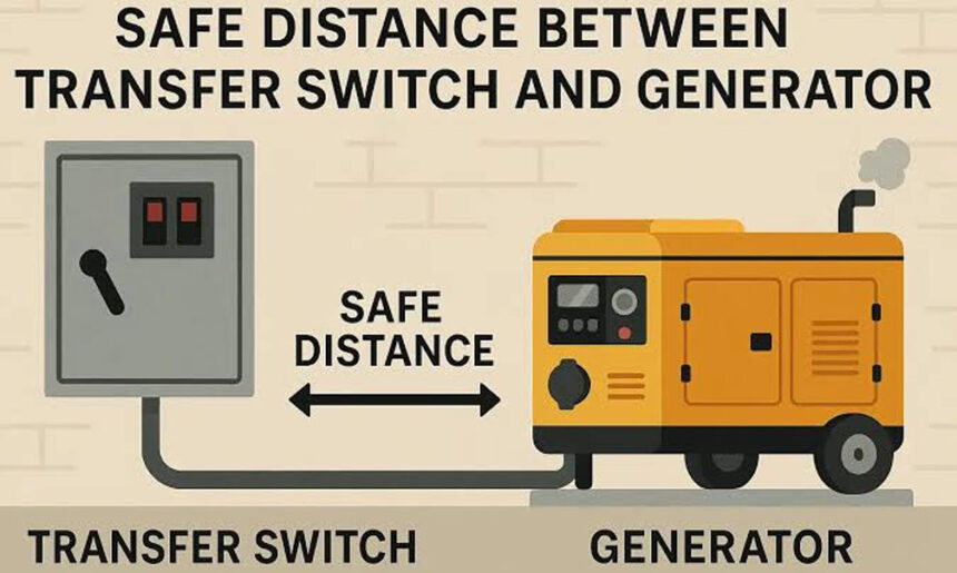
An automatic transfer switch (ATS) senses outages, starts the generator, and moves selected loads to the standby source. A service-rated ATS replaces your main disconnect and feeds the entire panel, while a non-service-rated ATS typically works with an upstream breaker. If you prefer to support only essentials, a dedicated subpanel fed through a smaller ATS keeps the generator size down. Load-shedding modules can drop noncritical circuits like a second-stage AC or electric oven during high demand, then restore them when the compressor winds down. Networked demand controllers coordinate starts so two big motors do not slam the generator simultaneously.
There are trade-offs. Whole-house transfer feels seamless but usually requires a higher kW rating or advanced load management, and sometimes a liquid-cooled platform for long duty cycles. An essential-circuit approach costs less power-wise but requires careful selection of which branch circuits migrate to the subpanel. Interlock kits paired with a manual transfer solution exist, but they demand disciplined operation and utility lockout provisions to satisfy code and prevent dangerous backfeed. For most homeowners who want automatic, unattended performance, a listed ATS matched to the service entrance and a clearly documented load-shedding plan keep the system safe and predictable.
-
Plan the Placement: Clearance, Exhaust, Base, and Noise
Site the generator on a level, noncombustible pad with proper drainage. Maintain manufacturer clearances from walls, soffits, and vegetation, and keep distance from windows, doors, and dryer or furnace vents to limit carbon monoxide intrusion. Aim the exhaust away from occupied areas and neighboring properties. Confirm local setback rules and HOA requirements. Provide a direct conduit path between the generator, the ATS, and the grounding electrode system, and route the gas line to avoid sharp bends and future landscaping conflicts. Think about the service side of the cabinet so technicians can open the lid and access filters, plugs, and the control board.
Noise planning is more than a spec sheet. Reflective surfaces like masonry can bounce sound toward bedrooms, and corner placements can create echoes. On a tight urban lot, a side yard with soft landscaping may sound quieter than a narrow alcove. In snow country, avoid placements where drifting buries vents or where downspouts dump onto the pad and form ice. In flood-prone areas, elevate the base above historic high water and anchor it to resist flotation. Small choices here help on the first stormy night, when the generator starts at 2 a.m., and the main bedroom window is nearby.
Commissioning and Periodic Verification Keep Standby Power Reliable
After installation, verify voltage and frequency stability under real household loads. Observe the ATS timing: start delay, transfer time, and retransfer when utility power returns. Confirm neutral bonding and grounding practices match the ATS type, and test any load shedding modules by intentionally starting large appliances. Check fuel pressures at idle and with the air conditioner engaged. Set the controller’s exercise schedule and, in cold regions, confirm crankcase heaters and battery maintainers are powered from a reliable circuit so the engine cranks quickly in freezing weather.
Routine readiness is not just a weekly no-load exercise. At least seasonally, simulate real demand by running the air conditioner, well pump, and oven while on generator power to confirm the governor and voltage regulator hold steady. Replace air filters and spark plugs per the manufacturer’s hours guidance, and change oil with the specified viscosity after heavy or dusty operation. Keep the battery terminals clean and the charger active. For propane systems, verify tank level before storm season and ensure regulators vent freely; for natural gas, note any appliance changes that could affect meter capacity. Record test results so you can spot declining performance before the next outage.
A standby generator performs as well as the plan behind it. When you list actual loads, respect motor starting currents, ensure the gas supply can support full output, select the right transfer gear, and place the unit thoughtfully, outages become routine rather than stressful. In most homes, that means choosing between whole-house transfer with managed loads and a lean essential circuit panel that keeps heat, water, and refrigeration running. Coordinating with a licensed electrician and a qualified gas fitter, and scheduling periodic under-load tests, will turn a specification on paper into dependable power when the lights go out.